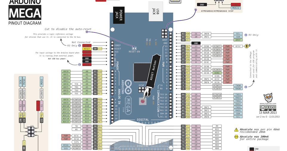
Each pin can provide/sink up to 40 mA max. In the Arduino Uno – pins 3,5,6,9,10,11 have PWM capability. Pin 13 of the Arduino Uno is connected to the built-in LED. Pins 0-13 of the Arduino Uno serve as digital input/output pins. This goes through the device’s ADC, gets converted into digital data, which is transmitted to the receiving side over the internet. Every smartphone has a microphone that converts sound waves (voice) into analog voltage. One common example of an ADC is Voice over IP (VoIP). The ADC converts voltage into bits which the microprocessor can understand. On Arduino the ADC has 10-bit resolution, meaning it can represent analog voltage by 1,024 digital levels. 
This digital representation of analog signals allows the processor (which is a digital device) to measure the analog signal and use it through its operation.Īrduino Pins A0-A5 are capable of reading analog voltages. ADC is an electronic circuit used to convert analog signals into digital signals. These pins serve as analog inputs but can also function as digital inputs or digital outputs.ĪDC stands for Analog to Digital Converter.

The Arduino Uno has 6 analog pins, which utilize ADC (Analog to Digital converter). It provides the voltage reference with which the microcontroller operates.
IOREF – This pin is the input/output reference. Always make sure that all GNDs (of the Arduino, peripherals and components) are connected to one another and have a common ground. The GND pins are used to close the electrical circuit and provide a common logic reference level throughout your circuit. In the Arduino Uno pinout, you can find 5 GND pins, which are all interconnected. They provide regulated 5 and 3.3v to power external components according to manufacturer specifications. When powering your circuit through the barrel jack or VIN, the maximum capacity available is determined by the 5 and 3.3 volts regulators on-board the Arduino. Take into consideration that this is also used for powering the MCU, its peripherals, the on-board regulators, and the components connected to it. For instance, powering the circuit using the USB limits you to 500mA. The power source you use determines the power you have available for your circuit. There is a polarity protection diode connecting between the positive of the barrel jack to the VIN pin, rated at 1 Ampere. USB cable – when connected to the computer, provides 5 volts at 500mA. The voltage should be within the range mentioned above. VIN Pin – This pin is used to power the Arduino Uno board using an external power source. Above 12 volts, the regulators might overheat, and below 7 volts, might not suffice. The board can be powered by 5-20 volts but the manufacturer recommends to keep it between 7-12 volts. The barrel jack is usually connected to a wall adapter. Barrel Jack – The Barrel jack, or DC Power Jack can be used to power your Arduino board. There are 3 ways to power the Arduino Uno: “ Pinout of ARDUINO Board and ATMega328PU” by pighixxx is licensed under Creative Commons Attribution-Share Alike 4.0 International Arduino Uno pinout – Power Supply Start Your Arduino Circuit Arduino Uno Pinout – Diagram In this post, we’ll go over the capabilities of the Arduino Uno pinout. The versatility of the pinout provides many different options such as driving motors, LEDs, reading sensors and more. The Arduino Uno pinout consists of 14 digital pins, 6 analog inputs, a power jack, USB connection and ICSP header. Arduino Uno is based on the ATmega328 by Atmel. 
In this post, we’ll be taking a closer look at the Arduino hardware, and more specifically, the Arduino Uno pinout. We saw that Arduino boards are programmed using a language derived from C and C++ in Arduino’s Integrated Development Environment (IDE) and learned a few basic debugging methods.

#ARDUINO MEGA PINOUT DIAAGRAM SOFTWARE#
In our last two posts, we focused on the software aspects of the Arduino.


 0 kommentar(er)
